Turbine Hall Design: From Foundation to Digital Twin
"A turbine hall is not simply a building with equipment inside. It is an integrated engineering system where every element, from foundation to ventilation, works in concert with the turbine unit. A layout or structural error can cost an enterprise months of downtime and tens of millions in losses."— Chief Project Engineer, 15 years of experience in thermal power facility design
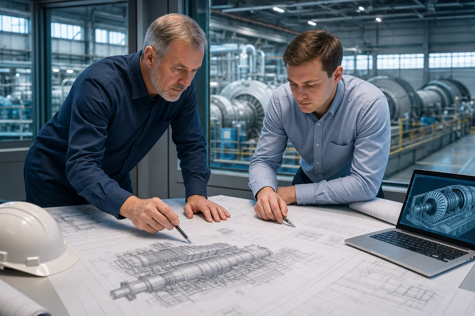
When it comes to power plant design, the spotlight usually falls on the "loudest" equipment: turbines, boilers, generators. But it is the turbine hall, the building housing all this machinery, that ultimately determines whether a plant will operate reliably, be easy to maintain, and successfully undergo major overhauls over its 30-50 year lifespan. This article provides a comprehensive overview of turbine hall design for thermal power plants and industrial facilities: from regulatory requirements and layout decisions to modern BIM technologies and digital twins.

Why the Turbine Hall Is the Most Critical Structure at a Power Plant
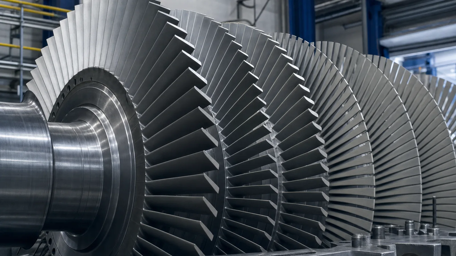
The turbine hall is the primary production building of a power station, housing turbine units, generators, condensers, oil supply systems, steam and condensate piping, and overhead cranes for installation and maintenance. It carries enormous dynamic and static loads while operating under conditions of elevated temperature, humidity, and vibration.
Unlike conventional industrial buildings, turbine halls must accommodate unique factors: constant vibrations from rotors spinning at 3,000 rpm (50 Hz), overhead cranes lifting 50-200+ ton components, and complex networks of high-pressure steam piping. Design errors in layout become evident throughout the plant's lifetime as maintenance difficulties, inability to replace major components, vibration problems, and piping failures.
Regulatory Framework
In Russia, turbine hall design is governed by VNTP 81 (Technological Design Standards for Thermal Power Plants), RD 34.15.078-91 (Turbine Unit Foundation Design Guidelines), GOST R 59182-2020, and various building codes (SP series). International standards from ASME, IEC, and VGB apply when working with imported equipment.
| Standard | Scope | Key Requirements |
|---|---|---|
| VNTP 81 | TPP technological design | Layout, dimensions, equipment placement |
| RD 34.15.078-91 | Turbine unit foundations | Dynamic calculations, vibration isolation |
| ASME PTC 6 | Steam turbine testing | Performance evaluation methods |
| IEC 60045 | Steam turbines | General technical requirements |
Layout Options: Where Real Engineering Begins
Layout is the decisive stage determining the plant's fate for decades. The main options include longitudinal arrangement (turbines along the hall axis, most common), transverse arrangement (perpendicular orientation, for compact industrial CHPs), island layout (separate buildings for modernization projects), and block layout (turbine hall combined with boiler house to minimize piping lengths).
Typical spans range from 24-30m for 50-100 MW turbines to 36-42m for 200-800 MW units. Clear height to crane rails varies from 15 to 25 meters. Dozens of factors influence layout selection: site terrain, prevailing winds, access roads, future expansion requirements, and maintenance access.
Foundations: Taming Vibration
Turbine foundations are not simple concrete slabs but complex structures carrying hundreds of tons of equipment, dynamic rotational loads, and thermal deformations. Block (massive) foundations suit smaller turbines up to 100-150 MW, while frame foundations with upper plates, columns, and condenser basements serve larger units. Approximately 35% of unplanned shutdowns at thermal plants relate to abnormal vibrations. Modern spring-damper isolation systems can reduce foundation acceleration from 1 m/s² to below 0.1 m/s².
Steel Structures and Overhead Cranes
The turbine hall frame is a steel portal structure supporting the roof, walls, crane runways, and maintenance platforms. Overhead crane capacities range from 30-50 tons for small industrial CHPs to 200-350+ tons for major power stations. Crane runway beam design must account for vertical and horizontal loads, fatigue from hundreds of thousands of loading cycles over 30-40 years.
Condenser Systems and Cooling
The condenser creates maximum vacuum at the turbine exhaust, directly affecting plant efficiency. Design involves thousands of tubes (stainless steel or copper alloys), proper placement beneath the turbine exhaust, and integration with cooling water systems. A 1 kPa difference between design and actual vacuum can cost millions annually in lost generation.
Oil Systems and Piping
The oil system ensures bearing lubrication, governor operation, and fire safety. With mineral oil flash point at ~370°C and live steam at 540-560°C, fire prevention is critical. Solutions include fire-resistant oils (flash point >700°C), protective shields, and automatic fire suppression. Steam piping routing must account for thermal expansion of tens of millimeters during warm-up.
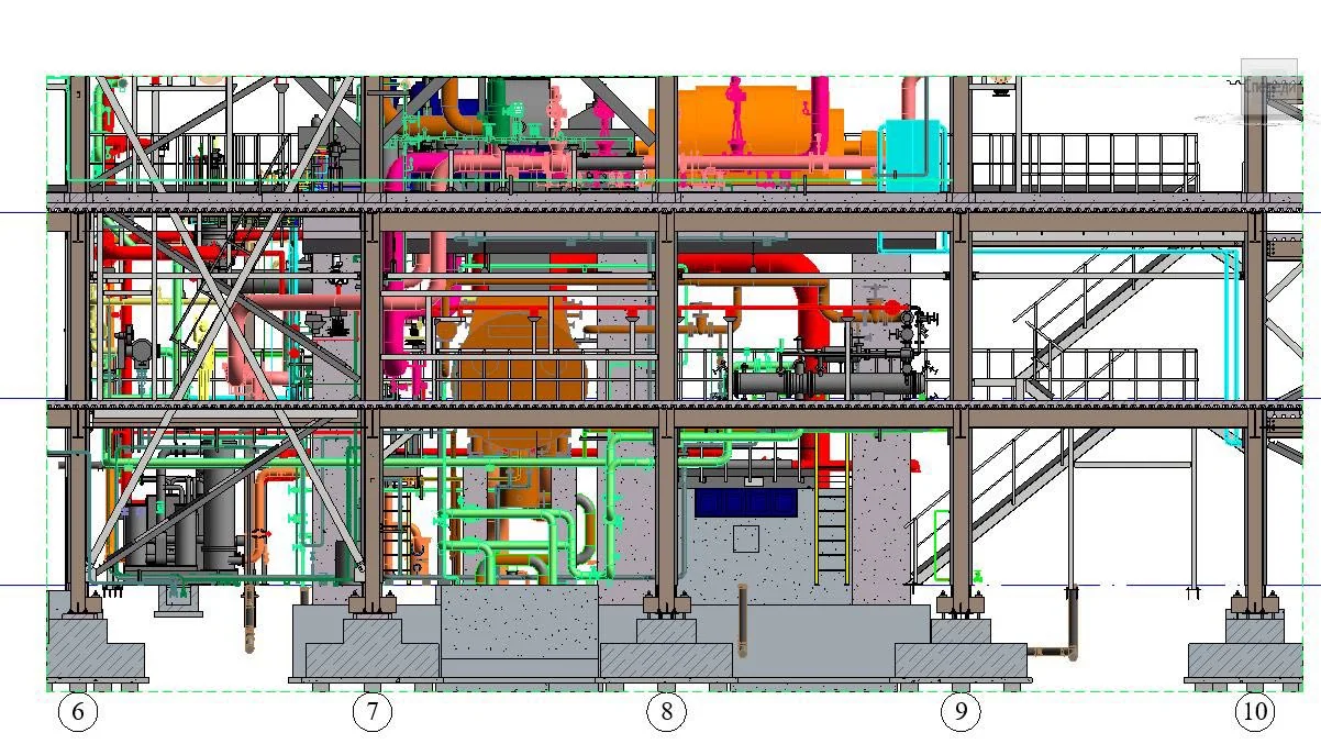
BIM Design and Digital Twins
BIM enables comprehensive 3D modeling that eliminates up to 90% of clashes before construction. Russian software (Model Studio CS, Kompas-3D, nanoCAD BIM) is increasingly replacing Western tools. Digital twins extend BIM models into operation, predicting equipment defects 120-144 hours in advance with model accuracy within 3% of real parameters.
Modernization and Future Trends
Russia's KOMMod program drives replacement of aging equipment across hundreds of plants. Current projects include 3.78 billion ruble modernizations at Ufa CHP-2 and similar programs nationwide. Key trends for 2026 include hydrogen readiness, modular construction (reducing timelines by 20-30%), operational flexibility, and renewable energy integration.